
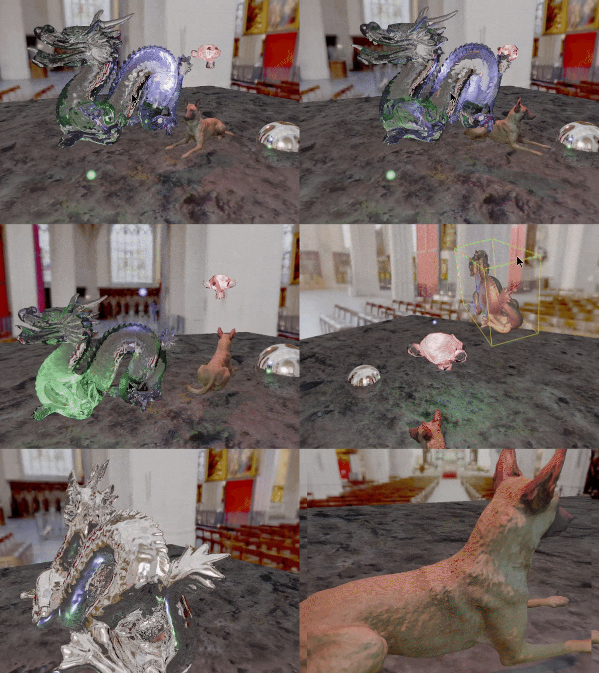

Interactive real time ray tracer written from scratch in C and C++ which can run on either a CPU or a GPU (using CUDA):
Physically based shading uses a microfacet BRDF model (Cook-Torrance, Schlick/Smith GGX) with a metallic workflow.
Point lights have volumetric-fog, quad geometries with an emissive material become area lights with soft lighting and soft shadows.
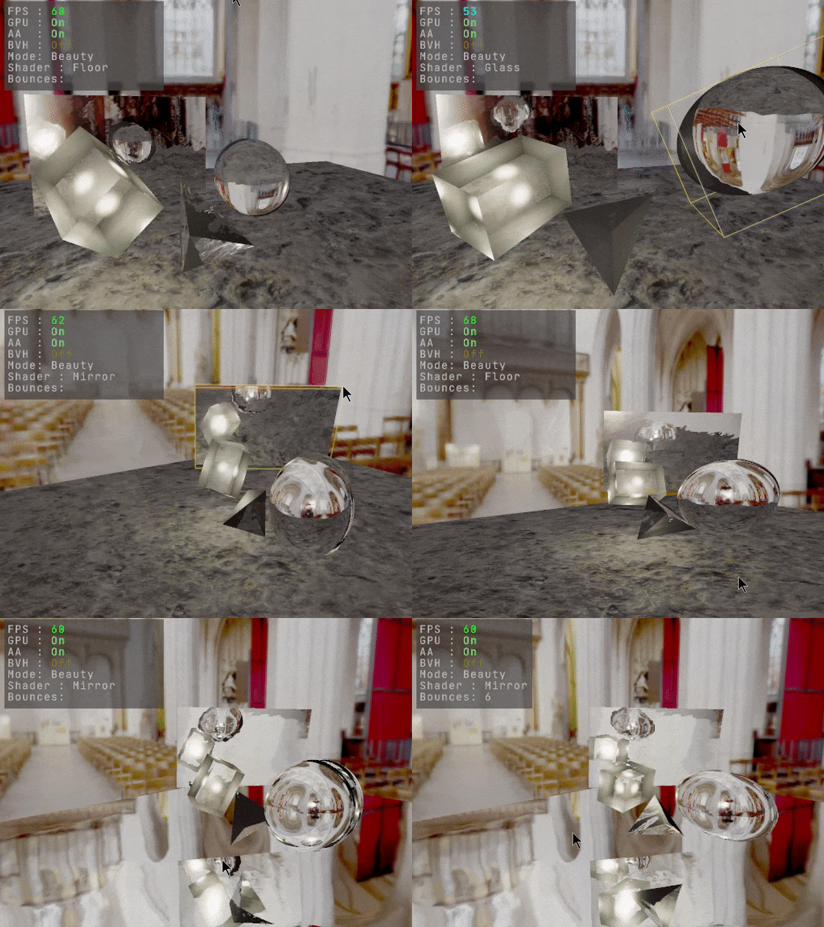
Multi-bounce reflections is supported, as well as multiple refractions (using index of refraction)
UV-based transparency is accounted for by shadow rays.
Implicit geometry types such as spheres, boxes and tetrahedra can be used as scene objects.
Scene and meshes have separate acceleration structures (BLAS vs. TLAS BVHs).
Mesh BVHs do not need to be rebuilt or updated when transformed, as tracing is done in local-space.
Texture filtering and sampling is done in software, using ray cones for adaptive mip-level selection.
Scene objects can be transformed using a unified manipulator that uses ray-casting against the selected object's bounding box.
Keyboard and mouse navigation supports both FPS-style navigation and DCC-style for panning zooming and orbiting the camera.

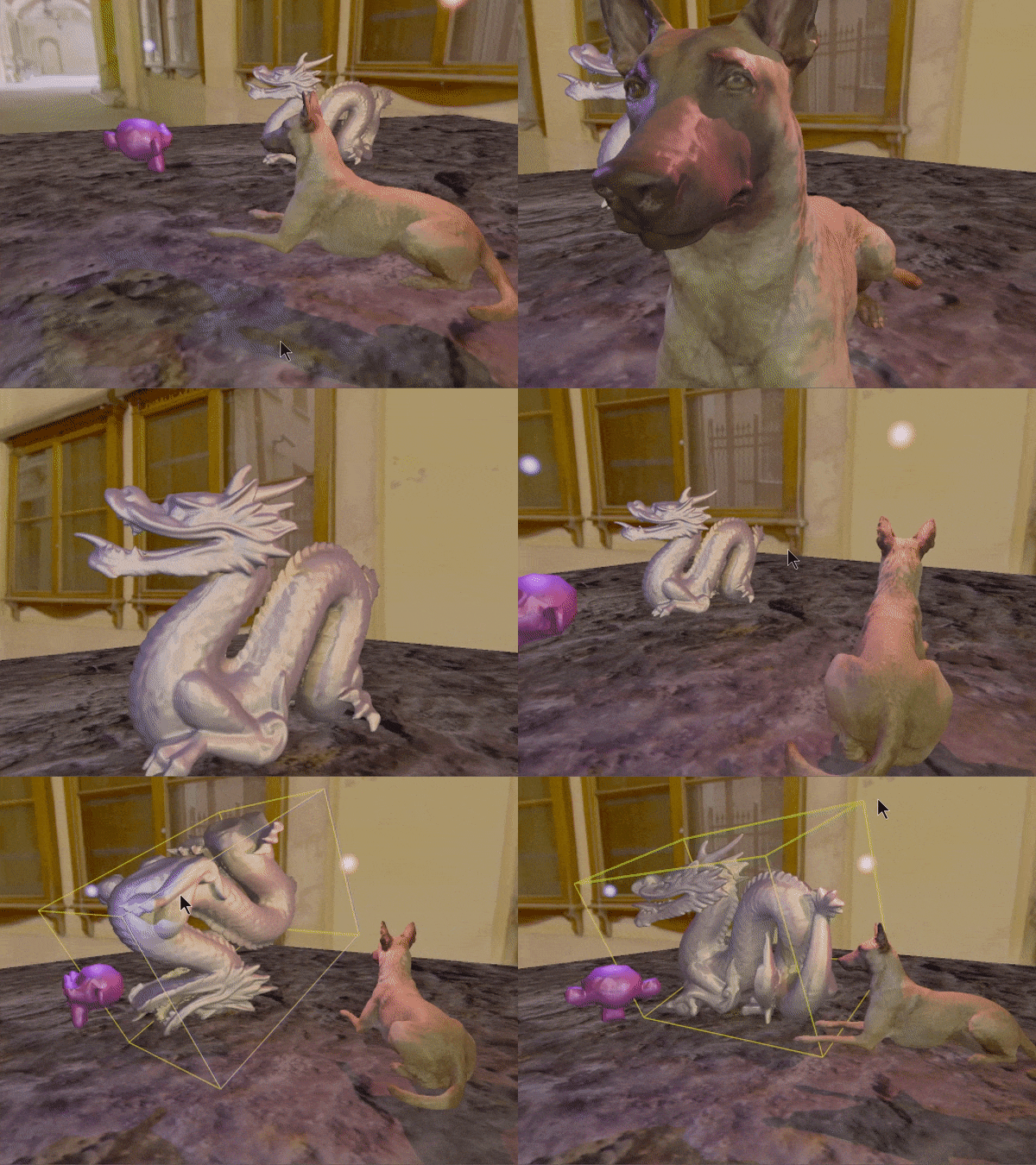


Volumetric Lights:
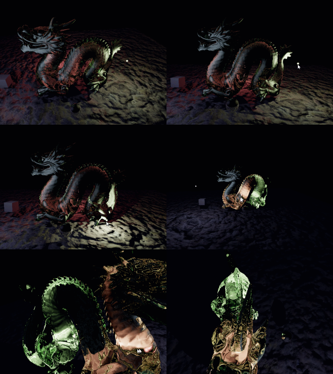

What started as a fun experiment to visualize point lights as they might appear in a fog, resulted in some happy accidents in how well it seem to work within a refractive glass-like surface. The approach uses an analytic integration of density along a ray within a sphere around a point light. The falloff and density in the integration is modulated by the scale and intensity of the point light.
This approach can be applied to any ray being traced in any media, for example, the refraction and internal-reflection rays within a glass mesh. This produces natural looking result of how fight from a small light source might interact with the glass from within. This is just a natural consequence of how multiple bounces of rays accumulate density along the overall path.
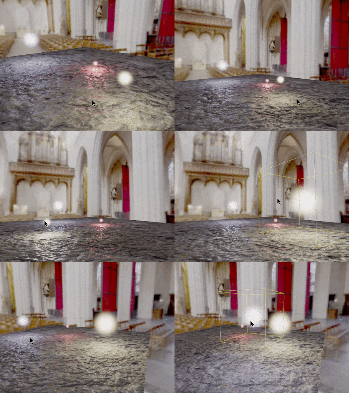


Area Lights:
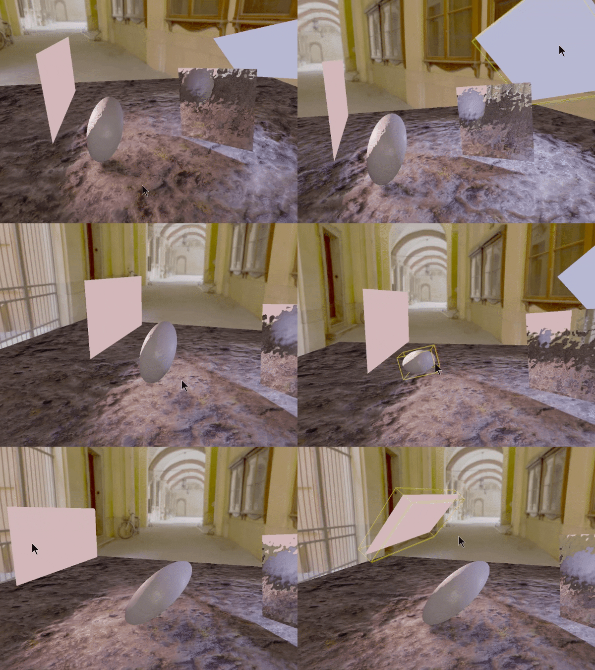

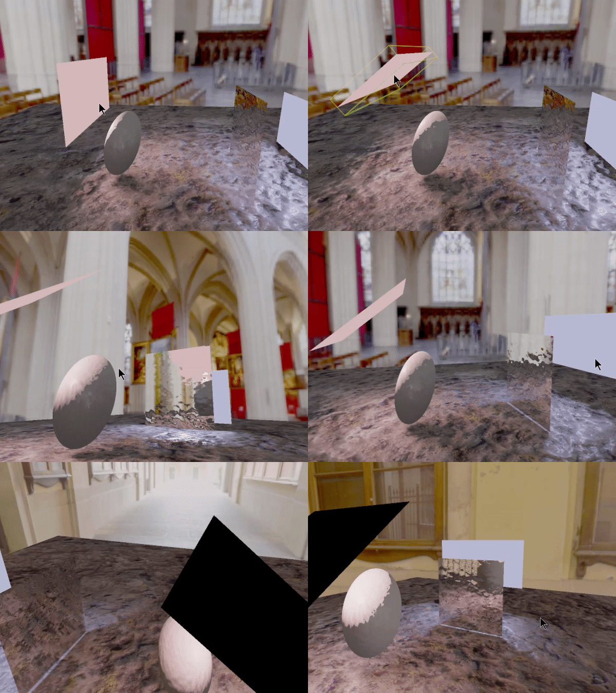
Lights in computer graphics can often be considered as emanating light from an infinitesimally small point in space. In reality though, lights always have a finite surface area that emits light, producing much softer light and shadows. However, simulating the real world in such a way is very expensive computationally. It would be difficult to render in real time, so approximations have been developed to try and produce 'plausible' looking soft lighting and shadows.
For soft lighting, one such approximation uses Linearly Transformed Cosines (LTC for short): An area light has a certain shape and size, and is oriented towards the point on the shaded surface at a certain angle and at a certain distance. All these factors are combined to compute the overall amount of light hitting the shaded point.
For soft shadows, each shaded point that is considered in shadow for a given light checks how far away it is from the bounds of where a sharp-shadow would have been if the area light had no surface area. This is then modulated multiplicatively by the same intensity measure computed for the soft-light LTC computation, so the shadow's softness also accounts for the size, distance and orientation of the area light, aimed towards the shaded point. Combining these approximations produces a result that feels natural in how the shading interacts with the area light.


Physically Based Shading:
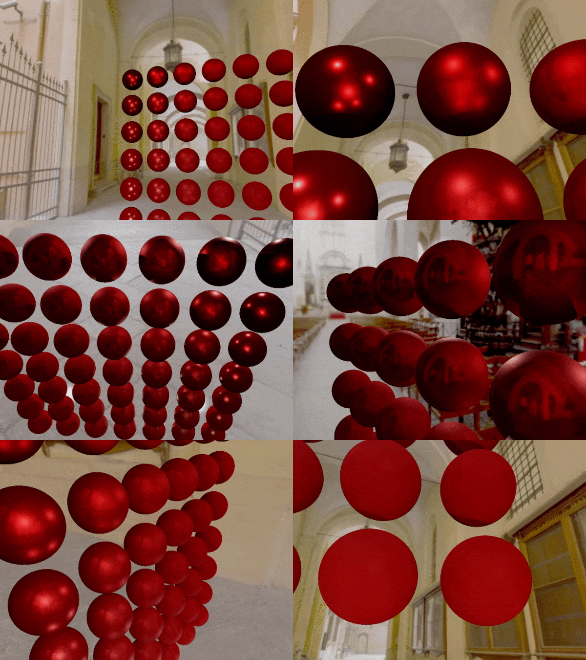

Physically based shading is used for materials using a Cook-Torrance BRDF model with the Smith GGX and Schlick Fresnel approximations

Normal Maps:

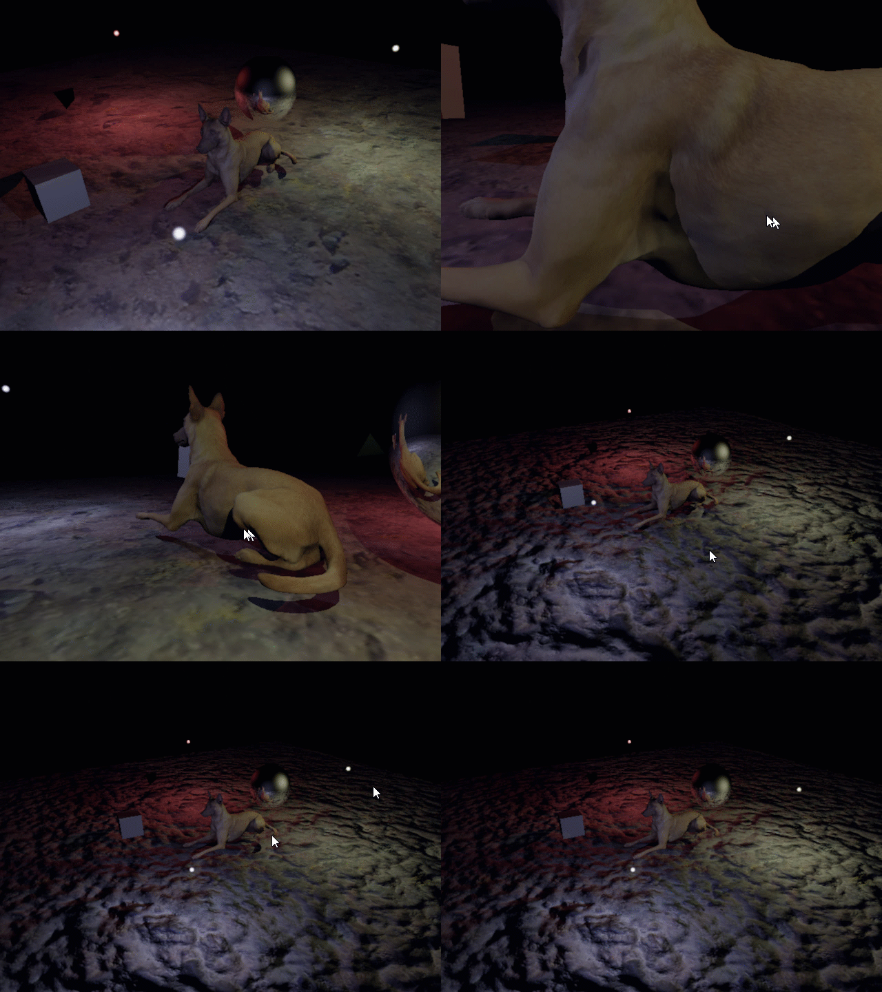
Shading can use normal maps to add fine details to flat surfaces. The normal direction on the surface hit point is rotated based on the sampled normal from the normal map.
Reflections / Refractions:
Reflections are trivial with Ray Tracing. Refraction uses Snell's law. Secondary and tertiary rays can be traced from hit points recursively up to a controllable trace-depth limit.
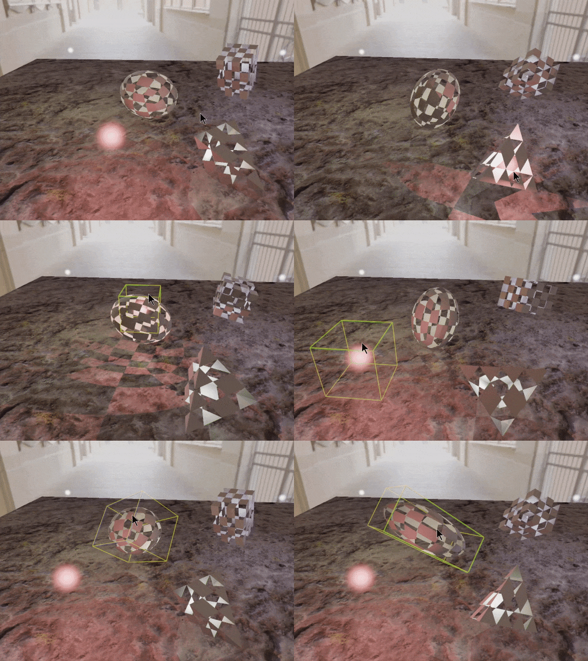

Transparency is also trivial in Ray Tracing, as rays can always miss a part in one geometry but then continue tracing forward until they hit another. This can apply for both light shading rays and shadow rays.
Transparency / Shadows:

Texturing is done using mip-maps which are the same texture at different resolutions. Sampling needs to be done from an image of an optimal resolution for each sampling point. In Rasterization, that is done using screen space derivatives. In Ray Tracing, there is no cheep way to compute such derivatives that work for rays of arbitrary trace depth.
Ray Cones is an alternative way to approximate the surface area of the sampled point on the surface as seen through the ray that had hit that point. Starting with primary rays, each ray is perceived to have a cone with a given span angle, whose tip is at the ray's origin and whose base is aiming at the ray's direction. The surface area of the hit point is computed from the cone's base there, accounting for the distance and angle of incidence. Comparing that surface area with the texture-space area covered by the cone-base, is used to inform what texture fidelity should be sampled for that hit. This is then used to select an optimal mip-level when sampling the texture.
This way of adaptive sampling is very resilient to changes in orientation and size of the surface, as well as to changes in texture coordinate space.
Ray Cones:
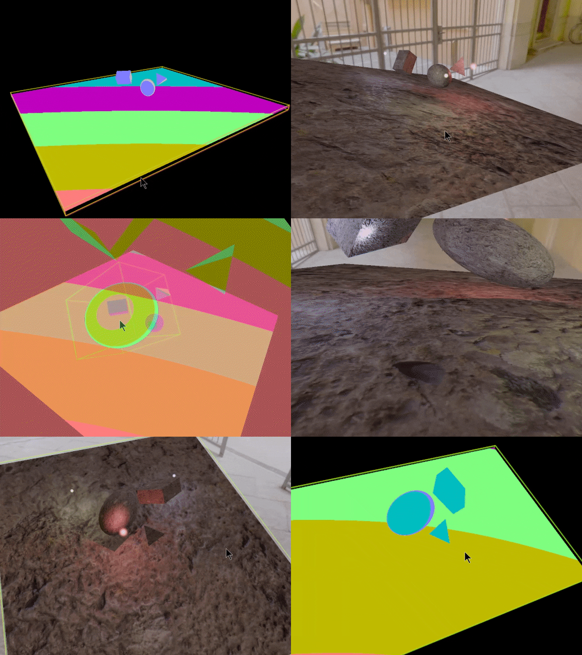

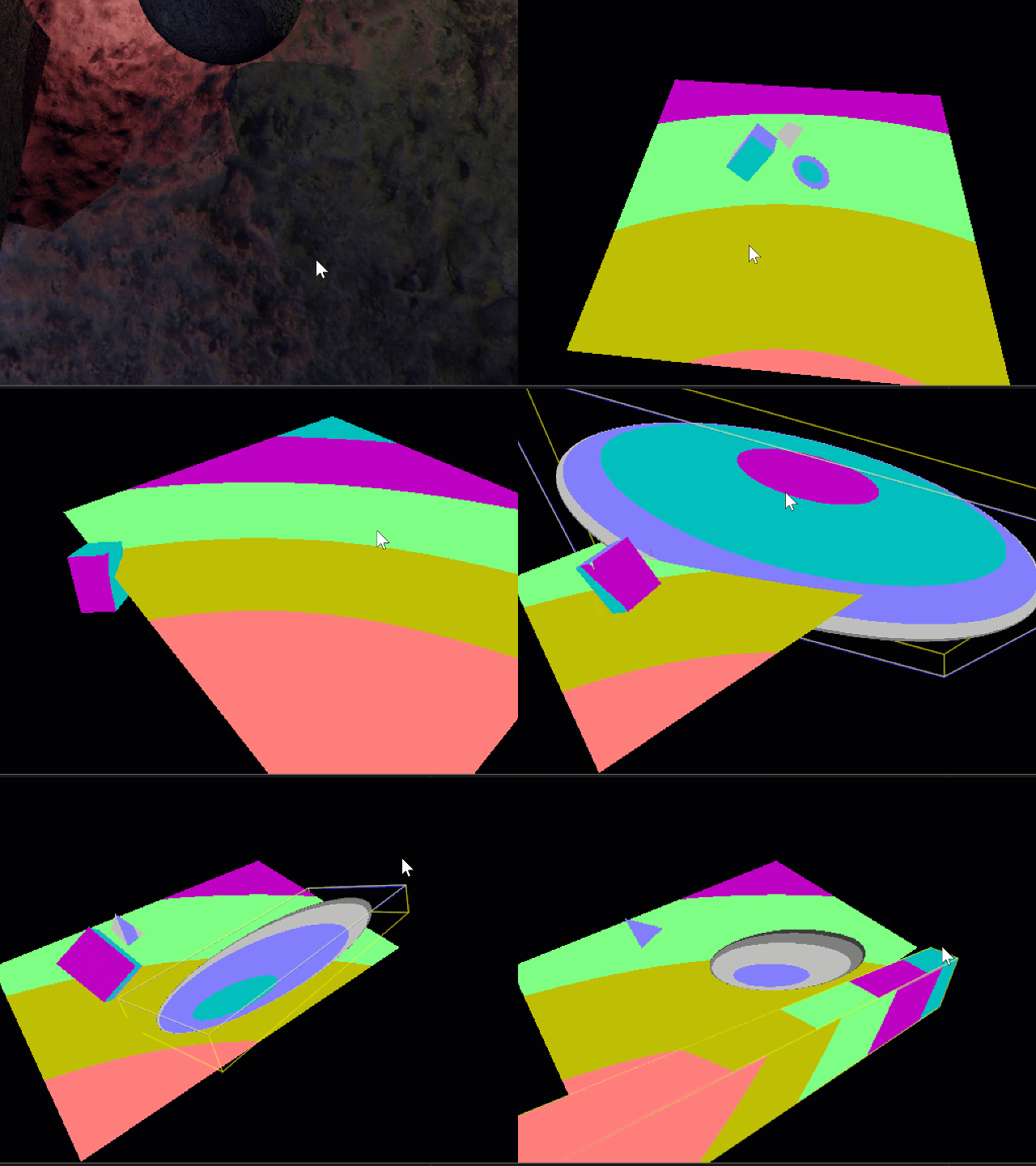


Rendering decent images often requires tracing millions of rays and decent meshes often contain many thousands of triangles. It would be infeasible to expect to trace every single ray through every single triangle to check for intersection (Big-O of N x M). Though given how in practice most rays would end up hitting just a few triangles and miss all the others, there are ways to avoid having to perform most intersection checks preemptively by using Acceleration Structures:
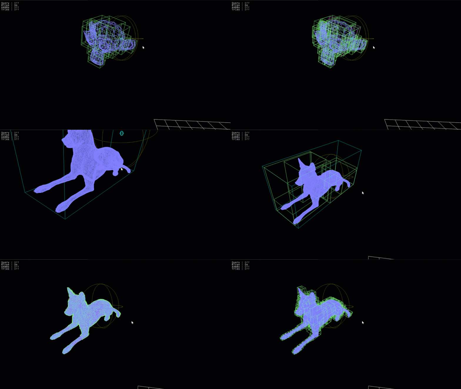
Instead of having rays traced against geometries directly, they are first traced against Acceleration Structures that select only the few pieces of geometry that each ray may actually end up hitting. There are different kinds of such Acceleration Structures but the most common one used for ray tracing is called a Bounding Volume Hierarchy (or BVHs for short) containing a Hierarchy of Bounding Volumes in the form of Axis-Aligned Bounding Boxes (AABBs for short). It is a Tree data structure that holds a hierarchy of nodes, where only the leaf nodes contain the actual pieces of geometry (all other nodes just contain child-nodes).
Tracing a ray against a BVH is done in the following way:
If a ray misses a node's AABB, it is considered to miss all the geometry in all the leaf-nodes under the sub-tree of that node.
If a ray hits a node's AABB, it continues to trace against all it's immediate children all the way to the leaf nodes at the bottom.
If a ray hits a leaf-node, it then gets traced against all geometries it contains using specialized ray/geometry intersections.
This is standard practice in the world of Ray Tracing and is how this ray tracer works under the hood.
There are actually 2 separate layers of Acceleration Structures:
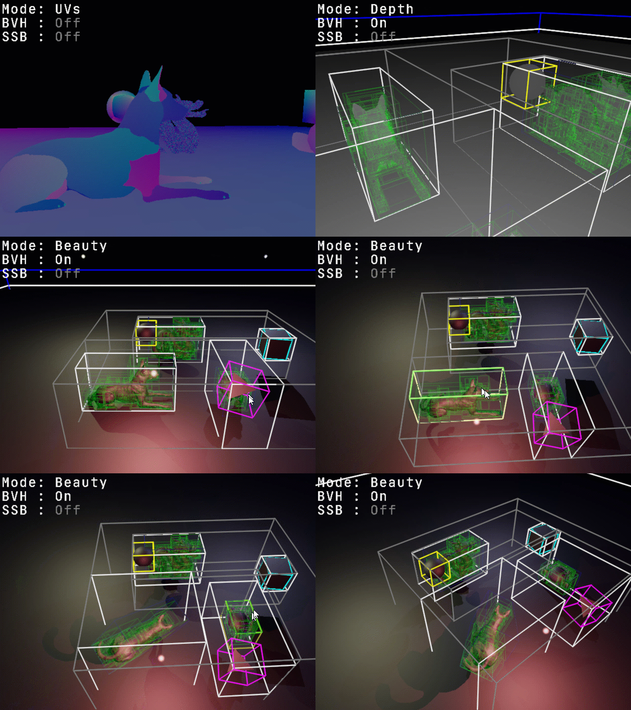
Top-Level Acceleration Structure (or TLAS for short) holds the entire scene itself as a whole (drawn here in white and grey)
Bottom-Level Acceleration Structure (or BLAS for short) exist for each specific mesh (drawn here in green)
BLASs themselves live within the leaf-nodes of the TLAS as though they were any other geometry type. This effectively forms a "hierarchy of hierarchies", where BLASs only get traversed at all if their outer-most AABB gets hit by a ray traced against the TLAS.
The TLAS gets updated dynamically as objects in the scene are transformed, while BLASs remain static even as their meshes are transformed. This is achieved by having the actual tracing done in "local space", where rays themselves get transformed into the space of the meshes (accounting for their local-transformations) and then ray-hits themselves get transformed back-out onto the global space of the scene, for shading. This avoids updating BLASs (mesh BVHs) at runtime, which can get very costly. BLASs only get constructed once, as part of an offline process that produces their respective mesh files. BVH construction is tuned to produce tree structures that at runtime would perform their acceleration optimally. This tuning process uses a Surface Area Heuristic (SAH for short) to choose the best child-node configuration at every level of the tree. The goal is to get the tree of AABBs to wrap-around as tightly as possible around the mesh's overall 3D shape.
Acceleration Structures:



CPU / GPU (Toggle):
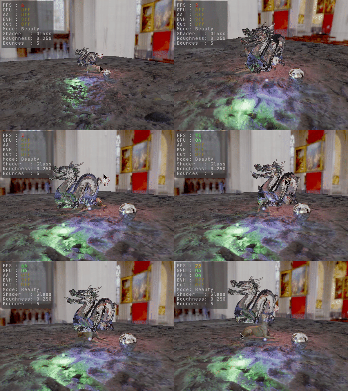

Depending on the compiler and scene complexity, frame rates can sometimes be low. But because the code is portable it can run on the GPU using CUDA, and can even be toggled dynamically between running on the CPU or the GPU at runtime. BVH trees are structured using indices instead of pointers, so uploading them to the GPU just means copying their buffers. Traversal logic is coded non-recursively, so there are no recursion limits imposed. Most of the traffic from the CPU to the GPU happens at startup. After that, only changes are being uploaded if and as they occur. The TLAS BVH gets uploaded only when the scene changes by any geometry transformation. Scene geometry transforms, material attributes, camera and render settings also only get uploaded as they change. CUDA features used are limited to defining and launching kernels, and copying memory, so that porting to OpenCL would be trivial.
